Electromagnetic Interference (EMI) is a disturbance that caused by electromagnetic fields that disrupt the normal operation of electronic equipment. It can affect signal transmission, cause errors in sensors, loss of data or even damage devices.
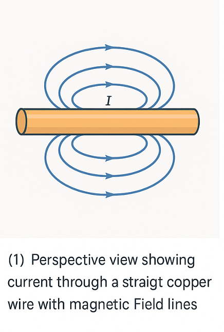
When electric current flows through a conductor, drifting electrons create both electric fields (from charge) and magnetic fields (from motion). Together they form an electromagnetic (EM) field that extends into the surrounding space.
When current flows through a straight copper wire, it produces circular magnetic-field lines around the wire.
The EM field that is generated by the flow of electrons can couple into other conductive materials in the surrounding, inducing unintended voltages and currents.
When a radio transmitter drives high-frequency alternating current through its antenna, that current generates oscillating electric and magnetic fields that detach from the metal and radiate outward as an electromagnetic wave.
When the wave reaches a nearby receiving antenna, the time-varying fields induce corresponding currents in the receiver’s conductors (Faraday’s law), recreating the original signal that the transmitter launched.

Unwanted electromagnetic fields in the vicinity of a circuit or antenna generate electromagnetic noise that degrade a device’s ability to interpret signals accurately, reducing both signal fidelity and overall efficiency. This phenomenon is known as electromagnetic interference (EMI).
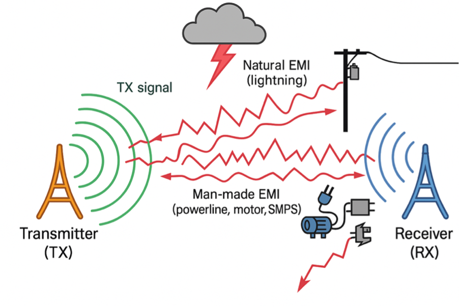
In the figure below, a transmitter emits the intended signal (shown in green). Stray electromagnetic fields from lightning strikes and nearby electrical equipment (illustrated in red) overlap the signal, introducing EMI that distorts the waveform before it reaches the receiver.
Water: The Hidden Piece of the Puzzle
Water is a strong attenuator of electromagnetic waves- especially at the high-frequency bands used by most modern telecommunication systems. Only very low frequency (VLF) signals penetrate seawater, which is why shore-based VLF stations are employed to communicate with submerged submarines.
You might assume that water’s filtering action keeps electromagnetic interference (EMI) around an ROV low, but in practice that is not the case.
Several factors combine to elevate EMI levels in deep-water operations.
Exploring deep water demands hundreds of meters of tether. On land you could switch to RF and eliminate the cable or tether need, but underwater that isn’t possible, so the entire copper length of the tether remains.
Because seawater blocks high-frequency radio, the tether is the only communication path. Its long length hangs through water and acts as a “sail,” generating drag. Operators leave slack to preserve maneuverability, but that extra loop area also increases the cable’s susceptibility to EMI.
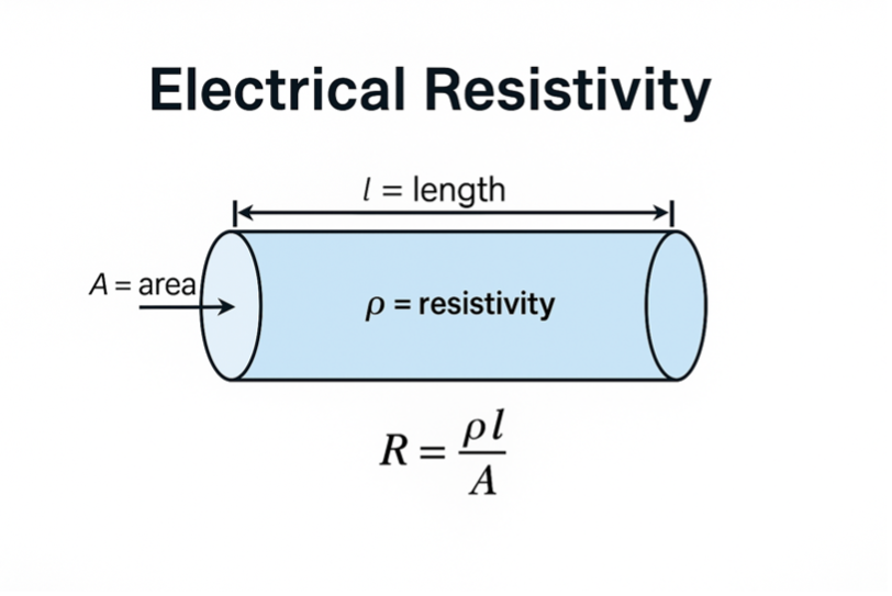
Every extra meter of tether cable adds series resistance and loop area. Higher resistance leads to larger voltage drop and higher current draw. Larger loop area leads to stronger radiated magnetic fields. Both effects scale almost linearly with depth, so length dominates the EMI intensity.
High current surges are also a topic to be considered. Thrusters and lights draw sharp current spikes (moving water is far harder than moving air). Those pulses couple into the data pairs and radiate along the cable. The ROV’s operation- amping up the lights, sending power to the engine and data through the tether to the TOP-SIDE causing unwanted EMI that affects the overall performance.The last topic to be considered is Hydrostatic pressure that affects the cable. water is denser than air and as we are diving deeper, the applying hydrostatic pressure upon the tether is growing bigger. External pressure compresses insulation, deforms the braid or foil, and can force seawater into micro-cracks, raising shield impedance and leakage paths.
So how do we tame underwater EMI?
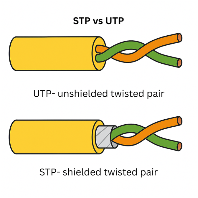
Use a high-quality tether with an additional aluminium foil shield wrapped over the twisted pairs. The foil presents a low-impedance path for high-frequency currents, shunting external EMI to the drain wire before it can couple into the signal conductors. With less noise on the line, differential data can travel farther and with fewer errors.
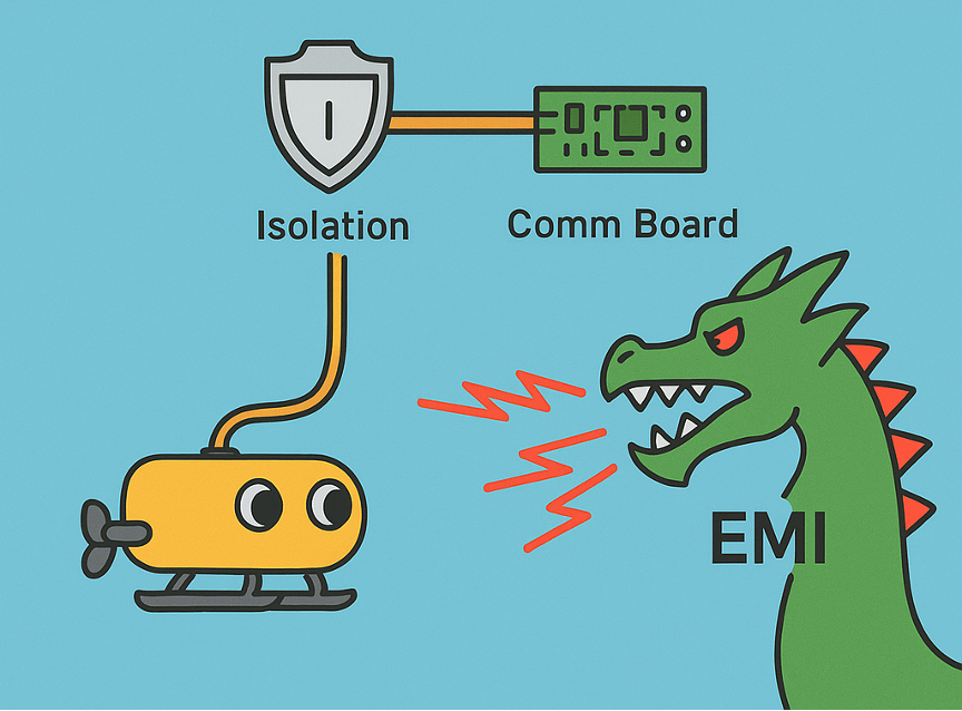
Sophisticated boards
as technology advances, the boards delivering the signals becoming more powerfull and potent for EMI. Thay are utilizing high output signals and filter out any noise intrudced to the tether by EMI.
For summery, exploring the depths poses many challenges. As ROV pilots and opreators we have to address the physical complexity of underwater communication.
If you are interested in exploring depths greater than 300 meters, I highly recommend using a tether that has shielded twisted pair (STP) and upgrade your communications board.
For depths greater than 500 meters I highly recommend taking into consideration fiber optic data transfer methods as they are less affected by EMI and allow the transfer of data at higher rates for longer distances relative to twisted pair method.